SWISS APPROVAL, Leader in Corrosion Mapping activities
Swiss Approval Advanced NDT based in UK, manages evaluation of the condition, the so called Corrosion Mapping, of storage tanks, pipelines, pressure vessels, metallic structures of any kind, and other critical equipment, supporting the integrity management processes, to ensure effective and safe operation, through specific Automated Ultrasonic equipment for corrosion mapping.
Corrosion mapping, is performed either:
- Manualy with use of specific probes and sensors. We are using Phassed Array and TOFD probes and technology, dedicated to corrosion mapping activities, with advanced equipment using TFM geometrical representation of deffects.
- Semiautomatic with the use of specific scanners. The Phased Array and TOFD probes, are installed on specific scanners, depending of the nature of the metalic structure to be inspected. In very specific geometrical shapes, when probes and scanners are dificult to adapt, we also propose Pulse Eddy Current inspection, with flexible probes, able to adapt the inspection process to the specific structure to be inspected.
- Combination of the above. In many circumstanses, the combination of Manual corrosion mapping with Semiautomatic corrosion mapping, are necessary in order to improve productivity and facilitate the inspection reporting.
- Automatic, with use of robotic systems for large surfaces, horizontal or vertical scanning. Our solution provides nearly 100% coverage in a band up to 450 mm wide, significantly increasing Probability of Detection (POD) of internal flaws and corrosion, enabling Clients to determine the optimum repair strategy, and improve remaining life assessment (RLA) & risk based inspection (RBI) maintenance programs.
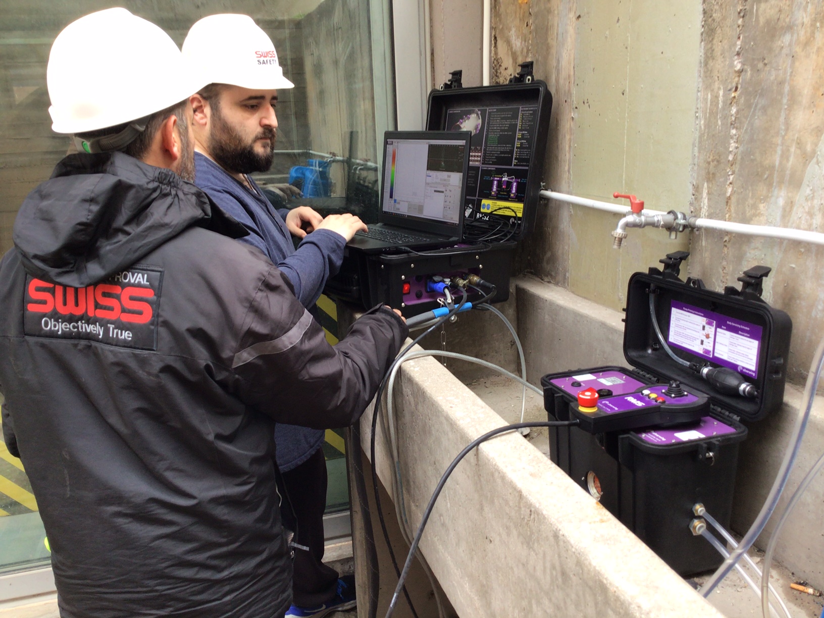
Automated Scanning: The Robotic Flexible Solution
Scanning heads of the system, sharing the same high performance system controller, so different scanning heads can be utilised depending on the inspection requirements.
The steerable tractor units incorporate high torque stepper motors and powerful magnetic drive wheels ensuring the scanner remains fixed to the inspection surface even whilst inverted. The system is properly working, to ride over weld caps & lap joints up to 8 mm high.
The Scanning Heads
Scanning head is designed to maximize scanning rates on large surface areas such as tank shells, pressure vessels and other structures, as well as operating circumferentially on curved surfaces such as pipelines or pressure vessels from 152 mm (6 inches) up to flat plate.
The Applications
- Storage tank shells and roofs
- Horizontal storage tanks
- Pipelines
- Pressure vessels
- Spheres
- Ship hulls
- High temperatures assets up to 200 C / 392 F.
The Detection Capabilities
- Localised / generalised pitting
- General corrosion and erosion
- Laminations
- Internal coating failures or dis-bonding
- Hydrogen blistering (HB)
- Hydrogen induced cracking (HIC)
- Stress corrosion cracking (SCC)
- Microbiologically influenced corrosion (MIC)
The Acquisition and Analysis Software
A specific software integrates scanner control, data capture, data analysis and reporting tools. The software shows a real-time display of the ultrasonic A-scan, C-scan, thickness measurement and positional data, with a maximum resolution of 0.5 mm x 0.5 mm. All this information is recorded when a scan is saved.
A-Scan Processing
A-scan waveform processing is fully digital, both in real time and during post processing.
Our system records A-scans in raw RF unfiltered form, which can then be processed afterwards, including rectification, filtering, wave smoothing and noise rejection. This minimises the set up on site and avoids re-scanning due to incorrect ultrasonic setup.
B-Scan Amplitude
The B-scan amplitude view shows the B-scan profile in both X and Y dimensions at a selected point of the C-scan. Using the B-scan amplitude view, the operator can easily identify any defects or inclusions.
C-Scan Layers & Multiple A-Scan Gates
The intuitive software is designed around the concept of C-scan ‘layers’. This allows the operator to quickly switch between each of the multiple C-scan views generated. During an inspection, the A-scan trace, B-scan amplitude view and resulting C-scan image are shown within the software in real time providing immediate inspection feedback.
Calibration of the advanced NDT tools, are performed according the procedures, and our Advanced NDT Laboratory operations, are conformed with ISO 17025 requirements.